In diesem Artikel möchte ich beschreiben, wie man mit dem „zusammenstecken“ einiger Komponenten eine eigene grafische Auswertung über den Pull Verlauf von Docker Hub Images erstellen kann, die so aussehen könnte:
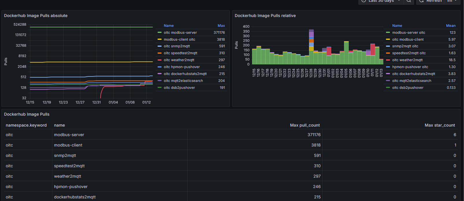
Der eigentliche Kniff ist nur, die Daten bei Docker Hub abzugreifen über die folgende URL:
https://hub.docker.com/v2/repositories/<namespace>/<name>
Architektur
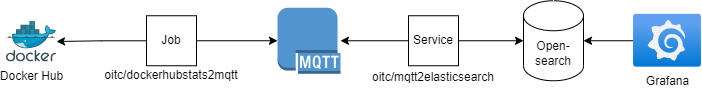
Wie man in dem Schaubild sieht, wird ein Job zyklisch die Metriken von Docker Hub lesen und in einen MQTT Server pushen. Ein Dienst wird auf die entsprechenden Topics hören, ankommende Daten abgreifen und in einer Opensearch (oder Elasticsearch) Datenbank abspeichern. Ab da kann man diese bequem mit Grafana auslesen.
In meinem Tutorial werde ich Opensearch verwenden, aber die Verwendung von Elasticsearch ist analog möglich wird aber im nachfolgenden Tutorial nicht weiter erwähnt.
Warum so kompliziert? Nun ja, ich habe einen zentralen MQTT Server im Einsatz, der bei mir zu Hause dreh und angelpunkt für Datenaustausch darstellt, daher habe ich das entsprechend entkoppelt. Zudem gibt es anderen Diensten die Möglichkeit gleichzeitig die gesammelten Daten zu verarbeiten.
Umsetzung
Für die exemplartische Umsetzung verwende ich einen Linux Rechner mit vorinstalliertem Docker. Bitte achtet auf genügend Arbeitsspeicher, da die Opensearch Datenbank einiges benötigt. 4 GB sollten aber genügen.
Job
Um die Metriken abzugreifen, habe ich ein kleines Script geschrieben, welches mir die Metriken der Docker Hub Repositories abgreift und in einen MQTT Topic published. Das Script findet Ihr auch in meinem GitHub Repo: https://github.com/cybcon/docker.dockerhubstats2mqtt/blob/main/src/entrypoint.sh. Aus dem Repo heraus erstelle ich einen Docker Container, den Ihr hier findet: https://hub.docker.com/r/oitc/dockerhubstats2mqtt.Dieser ist einfach über Umgebungsvariablen zu konfigurieren.
Die Variable „REPOSITORIES“ enthält die Container Image Repositorie Namen auf die es einem ankommt bei der Visualisierung. Also von diesen werden die Daten gesammelt.Hierzu gibt man der Variable eine, mit Leerzeichen getrennte Liste mit der relevanten Repositories. Jeweils mit dem Docker Hub Namespace und dem eigentlichen Image Namen.
Docker-Compose Beispiel:
services:
  dockerhubstats2mqtt:
    restart: "no"
    user: 5241:5241
    image: oitc/dockerhubstats2mqtt:latest
    environment:
      MQTT_SERVER: test.mosquitto.org
      MQTT_PORT: 1883
      MQTT_TOPIC: com/docker/hub/repositories/metrics
      REPOSITORIES: oitc/dockerhubstats2mqtt oitc/mqtt2elasticsearch
      MQTT_RETAIN: true
      MQTT_TOPIC_REPO_EXTENSION: true
Beim starten des Containers wird das Skript die Daten sammeln und in den MQTT_TOPC publishen und sich dann wieder beenden. Das ganze triggere ich dann via Cron zyklisch, z.B. einmal am Tag:
0 1 * * * /usr/bin/docker compose -f /pathto/docker-compose.yml run --rm dockerhubstats2mqtt >/dev/null 2>&1MQTT
Als MQTT Server nehm ich, zur einfachheit halber, in diesem Tutorial den Testserver von Eclipse Mosquitto. Dieser ist erreichbar auf test.mosquitto.org:1883.
In einem echten Szenario sollte man hier einen eigenen Server aufsetzen.
Service
Um Daten aus einem MQTT Topic auszulesen und in eine Opensearch Datenbank zu speichern, habe ich auch schon vor einiger Zeit ein kleines Python Skript geschrieben, dass genau das macht. Ihr findet das Skript in meinem GitHub Repo: https://github.com/cybcon/docker.mqtt2elasticsearch/blob/main/src/app/bin/mqtt2elasticsearch.py. Auch aus diesem Repo heraus erstelle ich einen Docker Container den Ihr hier findet: https://hub.docker.com/r/oitc/mqtt2elasticsearch.
Das Skipt selbst wird gesteuert durch 2 Konfigurationsdateien. Die „mqtt2elasticsearch.json“ enthält dabei die Verbindungsdaten zu den jeweiligen Servern. Also dem MQTT Server von dem es die Daten bekommt und die Opensearch Datebank, in den es die Daten schrieben soll. Die andere Datei „mqtt2elasticsearch-mappings.json“ dagegen enthält die eigentliche Mapping von MQTT Daten zu Opensearch Index. Einstieg ist immer der MQTT Topic auf den das Tool hören soll und darin wird das Ziel spezifiziert, wohin die Daten geschrieben werden sollen und wie dies dann im Detail aussieht. Dieser „elasticBody“ Bereich ist aber optional. Er ist dafür da, der Datenbank die Entscheidung abzunehmen was es denn für Felder gibt und was für Daten darin enthalten sein werden. Wenn man das weglässt. entscheidet die Datenbak das selbst anhand der Daten.
Die Konfigurationsdatei für die Verbindungsinformationen sieht z.B. so aus (mqtt2elasticsearch.json):
{
"DEBUG": true,
"removeIndex": false,
"opensearch": {
  "hosts": [
     {
       "host": "opensearch-node1",
       "port": 9200
     }
  ],
  "tls": true,
  "verify_certs": false,
  "username": "admin",
  "password": "FooBarBaz-123"
  },
"mqtt": {
  "server": "test.mosquitto.org",
  "port": 1883,
  "tls": false,
  "protocol_version": 3
  }
}
Die Konfigurationsdatei für das Mapping von MQTT Topic und die Opensearch Datenbank sieht z.B. so aus (mqtt2elasticsearch-mappings.json):
{
  "com/docker/hub/repositories/metrics/#": {
    "elasticIndex": "dockerhub-repositories-metrics-{Y}-{m}",
    "elasticBody": {
      "settings": {
        "index": {
          "number_of_shards": 5,
          "number_of_replicas": 0
        }
      },
      "mappings": {
        "properties": {
          "timestamp": { "type": "date" },
          "user": { "type": "keyword" },
          "name": { "type": "keyword" },
          "repository_type": { "type": "keyword" },
          "status": { "type": "integer" },
          "status_description": { "type": "keyword" },
          "description": { "type": "text" },
          "is_private": { "type": "boolean" },
          "is_automated": { "type": "boolean" },
          "star_count": { "type": "integer" },
          "pull_count": { "type": "integer" },
          "last_updated": { "type": "date" },
          "last_modified": { "type": "date" },
          "date_registered": { "type": "date" },
          "collaborator_count": { "type": "integer" },
          "affiliation": { "type": "keyword" },
          "hub_user": { "type": "keyword" },
          "has_starred": { "type": "boolean" },
          "permissions": { "type": "object" },
          "media_types": { "type": "text" },
          "content_types": { "type": "text" },
          "categories": { "type": "object" },
          "immutable_tags": { "type": "boolean" },
          "immutable_tags_rules": { "type": "keyword" },
          "storage_size": { "type": "integer" }
        }
      }
    }
  }
}
Diese beiden Konfigurationsdateien legt man dann im Dateisystem ab und mounted diese als Volume in den Container.
Docker-Compose Beispiel:
services:
  mqtt2elasticsearch:
    restart: unless-stopped
    image: oitc/mqtt2elasticsearch:latest
    container_name: mqtt2elasticsearch
    volumes:
      - /path/to/mqtt2elasticsearch/etc:/app/etc:ro
    depends_on:
      - opensearch-node1
Opensearch / Elasticsearch
Ich glaube, die Opensearch Datenbank zu betreiben ist das kompizierteste an allem, da die ein wenig „Liebe“ benötigt und genügend Ressourcen (RAM). 😀
Docker-Compose Beispiel:
services:
  opensearch-node1:
    restart: unless-stopped
    image: opensearchproject/opensearch:3.4.0
    container_name: opensearch-node1
    environment:
      node.name: opensearch-node1
      discovery.type: single-node
      discovery.seed_hosts: opensearch-node1
      OPENSEARCH_INITIAL_ADMIN_PASSWORD: FooBarBaz-123
      bootstrap.memory_lock: true  # along with the memlock settings below, disables swapping
      OPENSEARCH_JAVA_OPTS: -Xms512m -Xmx512m # minimum and maximum Java heap size, recommend setting both to 50% of system RAM
    ulimits:
      memlock:
        soft: -1
        hard: -1
      nofile:
        soft: 65536
        hard: 65536
Grafana
Nachdem nun alle Vorbereitungen erledigt sind, widmen wir uns der eigentlichen graifschen Auswertung. Hierfür verwende ich Grafana. Das Tool wird häufig auch im Unternehmensumfeld eingesetzt und kann zwischenzeitlich mit vielen Datenquellen interagieren.
Docker Compose Beispiel:
services:
  grafana:
    container_name: grafana
    image: grafana/grafana:12.3-ubuntu
    restart: unless-stopped
    ports:
      - 3000:3000
Nach dem Starten von Grafana, kann man sich mit dem Browser auf http://<server>:3000 verbinden und mit dem Benutzername admin und dem Passwort admin anmelden.
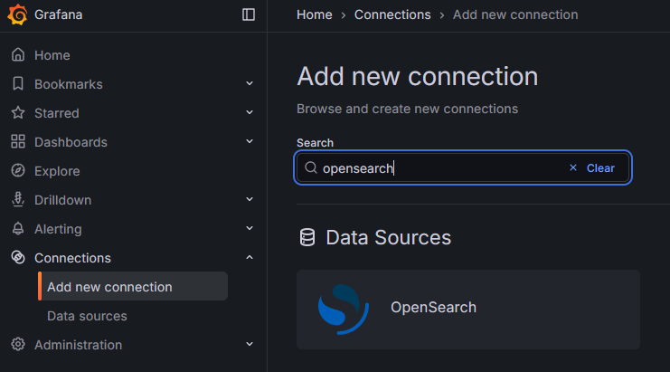
Zunächst brauchen richten wir die Datenquelle ein, also unsere Opensearch Datenbank. Hierfür gibt es im Grafana die Möglichkeit ein passendes Datenbank Plugin zu installieren. wir navigieren im Grafan im Menü zu „Connections“ > „Add new connection“. suchen dort nach „Opensearch“, wählen das Plugin aus und installieren dieses über den „Install“ Button.

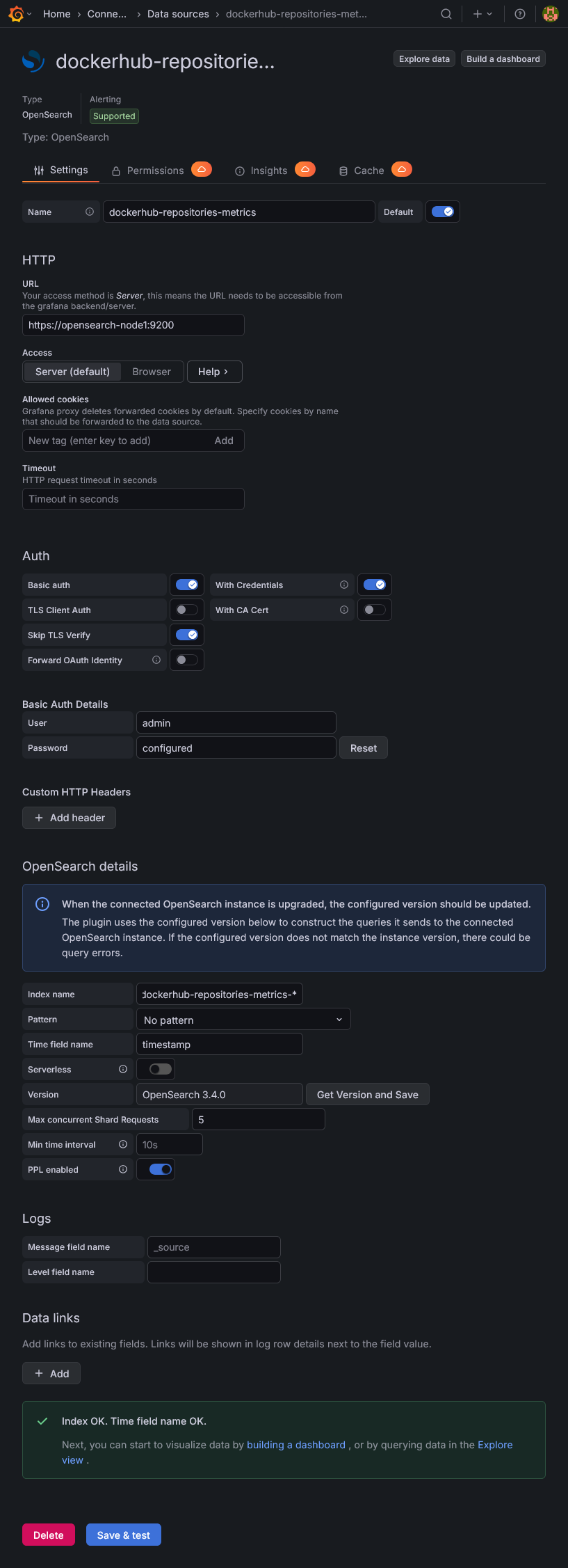
Nach der Installation des Plugins können wir die Datenbankverbindung selbst anlegen. Hierzu klicken wir entweder auf den Button „Add a new datasource“ nach der Plugin Installation oder Navigieren im Menü zu „Connections“ > „Data sources“ und wählen dort „Add data source“ und wählen hier „Opensearch“. Hier machen wir folgende Konfigurationen:
| Name | dockerhub-repositories-metrics |
| HTTP: URL | https://opensearch-node1:9200 |
| Auth: Basic auth | einschalten |
| Auth: With Credentials | einschalten |
| Auth: Skip TLS Verify | einschalten |
| Auth: Basic Auth Details: User | admin |
| Auth: Basic Auth Details: Password | FooBarBaz-123 |
| OpenSearch details: Index name | dockerhub-repositories-metrics-* |
| OpenSearch details: Time field name | timestamp (ohne das @ Zeichen) |
| OpenSearch details: Version | Auf „Get Version and Save“ klicken sollte die Version entsprechend finden. (hier OpenSearch 3.4.0) |
Nach Eingabe der Daten, sollte über Klick auf „Save & test“ alles gün sein.
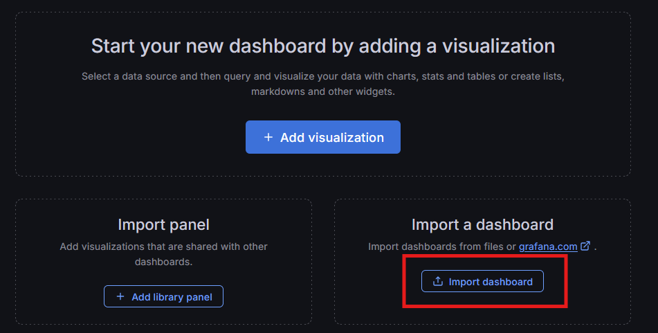
Danach richten wir das Dashboard ein. Hierzu navigieren wir im Grafana im Menü nach „Dashboards“ und Klicken hier auf „Create dashboard“. Nun haben wir die Wahl, ob wir komplett frisch anfangen wollen oder ob wir ein fertiges Dashboard importieren möchten. Das passende Dashboard habe ich bei Grafan hochgeladen und kann über ID: 24696 einfach importiert werden. Hier auch der Link zum Dashboard: https://grafana.com/grafana/dashboards/24696-docker-hub-image-pulls/. Daher klicken wir im Bereich „Import a dashboard“ auf den Button „mport dashboard“.
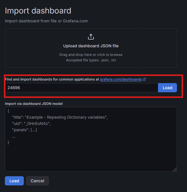
Auf dem nächsten Screen können wir die Dashboard ID (24696) eingeben und per Klick auf „Load“ das Dashboard laden.
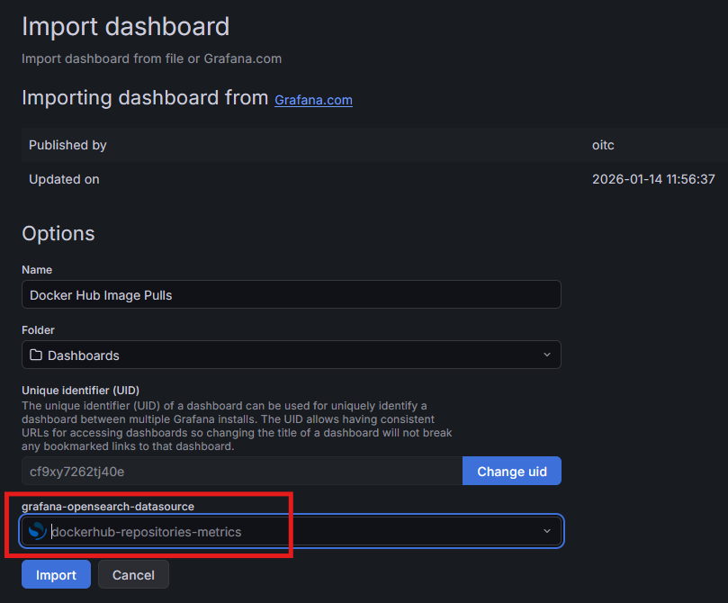
Auf dem daraufhin folgenden Screen müssen wir nur noch unsere vorher angelegte Datenquelle (dockerhub-repositories-metrics) auswählen und auf „Import“ klicken.
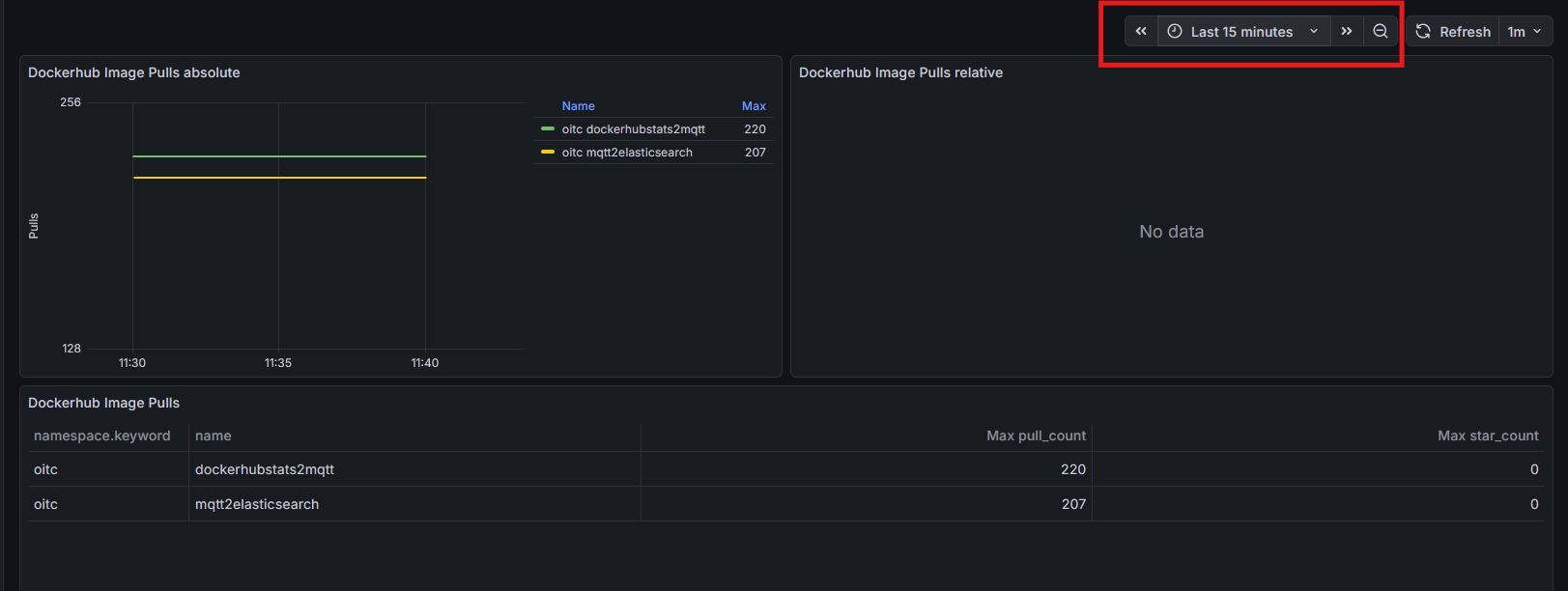
Dann sollte einem das Dashboard mit den Daten angezeigt werden. Sollten hier noch keine Daten auftauchen, kann man:
- das Tool dockerhubstats2mqtt einmal manuell aufrufen
- Den Zeitraum des Dashboards vom Default (30 Tage) auf zum Beispiel „Last 15 minutes“ einstellen.
Die gesamte Docker Compose Konfiguration
Da dies im Verlauf ein wenig zerstückelt war, hier nochmals die gesamt Docker Compose Konfiguration. Bitte beachtet, dass Ihr die beiden Konfigurationsdateien vom mqtt2ealsticsearch passend platzieren müsst und den Pfad bei „volumes“ dann richtig angeben müsst.
services:
  dockerhubstats2mqtt:
    restart: "no"
    user: 5241:5241
    image: oitc/dockerhubstats2mqtt:latest
    environment:
      MQTT_SERVER: test.mosquitto.org
      MQTT_PORT: 1883
      MQTT_TOPIC: com/docker/hub/repositories/metrics
      REPOSITORIES: oitc/dockerhubstats2mqtt oitc/mqtt2elasticsearch
      MQTT_RETAIN: true
      MQTT_TOPIC_REPO_EXTENSION: true

  mqtt2elasticsearch:
    restart: unless-stopped
    image: oitc/mqtt2elasticsearch:latest
    container_name: mqtt2elasticsearch
    volumes:
      - /path/to/mqtt2elasticsearch/etc:/app/etc:ro
    depends_on:
      - opensearch-node1

  opensearch-node1:
    restart: unless-stopped
    image: opensearchproject/opensearch:3.4.0
    container_name: opensearch-node1
    environment:
      node.name: opensearch-node1
      discovery.type: single-node
      discovery.seed_hosts: opensearch-node1
      OPENSEARCH_INITIAL_ADMIN_PASSWORD: FooBarBaz-123
      bootstrap.memory_lock: true  # along with the memlock settings below, disables swapping
      OPENSEARCH_JAVA_OPTS: -Xms512m -Xmx512m # minimum and maximum Java heap size, recommend setting both to 50% of system RAM
    ulimits:
      memlock:
        soft: -1
        hard: -1
      nofile:
        soft: 65536
        hard: 65536

  grafana:
    container_name: grafana
    image: grafana/grafana:12.3-ubuntu
    restart: unless-stopped
    ports:
      - 3000:3000
Hinweise
datenpersitenz
Dieses kleine Tutorial verwendet keinerlei Persistenz. D.b. wenn Ihr die Docker Container wegwerft oder erneuert, dann sind die gesammelten historischen Daten auch weg.
- Bei Grafana sind die Daten im Container Image an der Stelle „
/var/lib/grafana„. - Bei Opensearch sind die Daten im Container Image an der Stelle „
/usr/share/opensearch/data„
Passwörter und Zugänge
Das sind ganz einfache Beispiel, bitte verwendet richtige Passwörter. Im Unternehmenskontext sollte man auch nicht mit dem „admin“ user arbeiten sondern dedizierte Accounts anlegen die eben auch nur die Rechte haben, die benötigt werden.
TLS Zertifikate
Die Verbindungen sind alle unverschlüsselt bis auf die Verbindung zur Opensearch Datenbank. Und Opensearch verwendet ein selbst generiertes Zertifikat. In einer „echten“ Umgebung im Unternehmenskontext verwenden die Tools auch „echte“ Zertifikate um den Netzwerkverkehr abzusichern. Hier wird auch die TLS Validierung nicht deaktiviert.
Links
- Dockerhubstats2mqtt
- GitHub Repository: https://github.com/cybcon/docker.dockerhubstats2mqtt
- Image bei Docker Hub: https://hub.docker.com/r/oitc/dockerhubstats2mqtt
- Mqtt2elasticsearch
- GitHub repository: https://github.com/cybcon/docker.mqtt2elasticsearch
- Image bei Docker Hub: https://hub.docker.com/r/oitc/mqtt2elasticsearch
- Grafana
- Produktseite: https://grafana.com/grafana/
- Docker Image bei Docker Hub: https://hub.docker.com/r/grafana/grafana
- Informationen zur Grafana Docker Konfiguration: https://grafana.com/docs/grafana/latest/setup-grafana/installation/docker/
- Opensearch
- Produktseite: https://opensearch.org/platform/opensearch-core/
- Docker Image bei Docker Hub: https://hub.docker.com/r/opensearchproject/opensearch
- Eclipse Mosquitto
- Produktseite: https://mosquitto.org/
- Docker Image bei Docker Hub: https://hub.docker.com/_/eclipse-mosquitto